Tadalafil entfaltet seine Wirkung über eine selektive Hemmung der PDE5, wodurch die Konzentration von cGMP im glatten Muskelgewebe stabil bleibt. Diese biochemische Modulation resultiert in einer langanhaltenden Relaxation der Gefäßwände. Der Wirkstoff wird nach oraler Einnahme effizient resorbiert, mit einer Bioverfügbarkeit von rund 80 %. Seine Halbwertszeit von bis zu 36 Stunden ist innerhalb dieser Substanzklasse außergewöhnlich. Abgebaut wird er in der Leber, hauptsächlich durch CYP3A4, mit anschließender biliärer Exkretion. Typische unerwünschte Wirkungen entstehen durch eine verstärkte Vasodilatation, etwa Kopfschmerzen oder Flush. Pharmakologisch wird cialis generika vor allem durch die verlängerte Wirkungsdauer charakterisiert.
Classiccmp.org
Regulator ICs
Trickle-charge IC for two-cell, lithium-ion batteries BA3170
The BA3170 is a trickle-charge IC developed for two-cell, lithium-ion batteries.The IC includes a charge control circuit,a charge output transistor, and an LED driver for showing the charging status.
FApplicationsLithium-ion (two cell) battery chargers, and charging circuits
FFeatures1) Output voltage can be varied using an external resis-
5) Built-in over-discharge battery return circuit.
6) Built-in charge fault protection circuit.
2) The output pin is PNP output with low saturation volt-
7) Built-in over-voltage battery operation circuit.
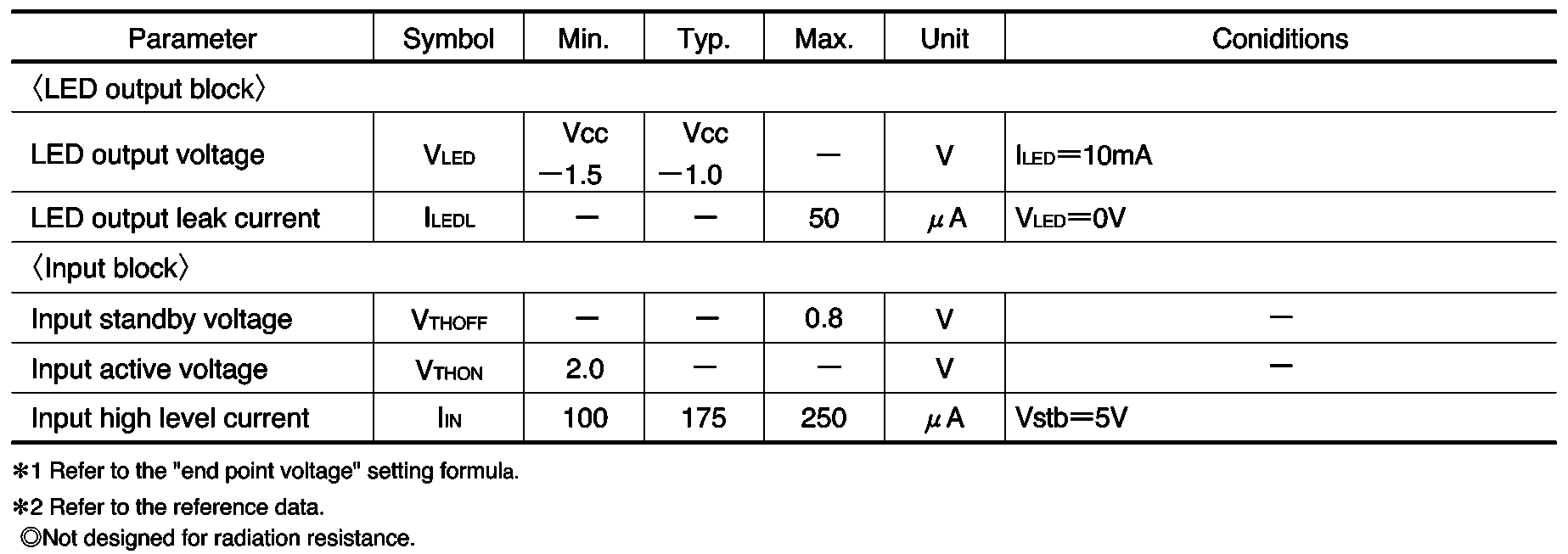
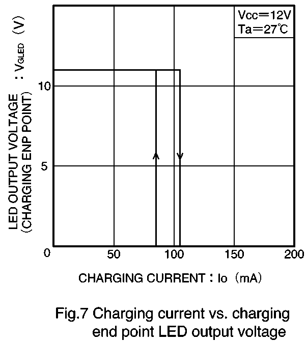
8) Built-in LED output for charge display (two outputs).
3) Built-in output current limiting circuit protects batter-
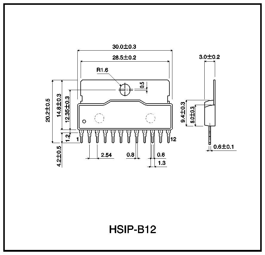
9) 12-pin power package provides large power dissipa-
ies from excessive current, and prevents destruction
10) Temperature protection circuit prevents thermal de-
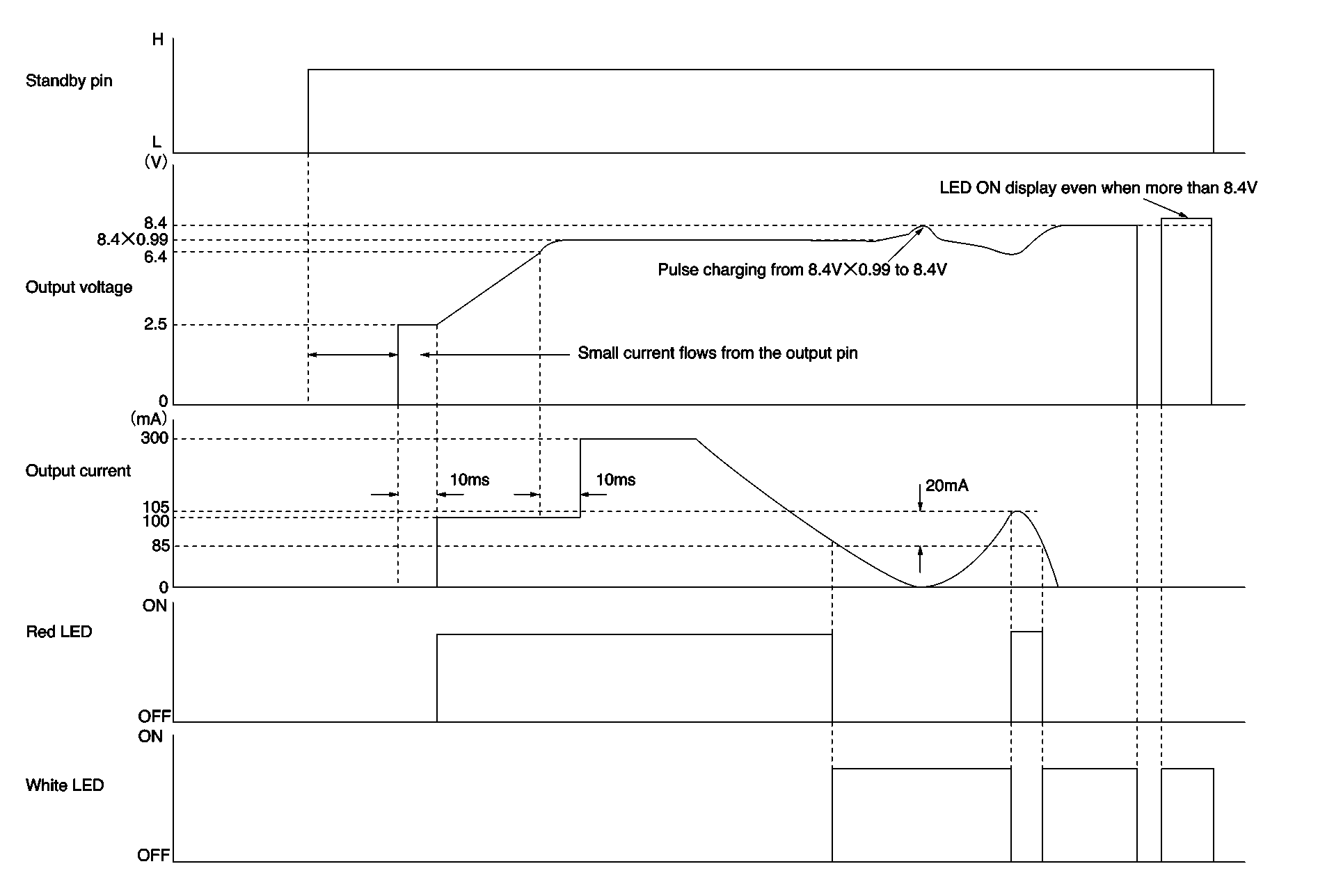
The initial charge current is set to a low value (the cur-
rent limit pin voltage can be used to vary the currentlimit value).
4) Pulse charging at over 99% of the final voltage.
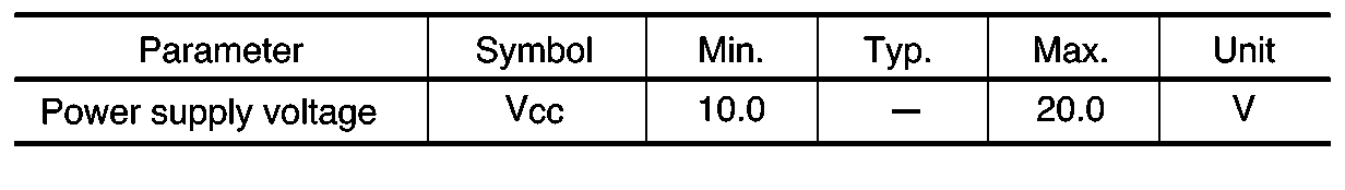
FRecommended operating conditions (Ta = 25_C)
Regulator ICs Regulator ICs
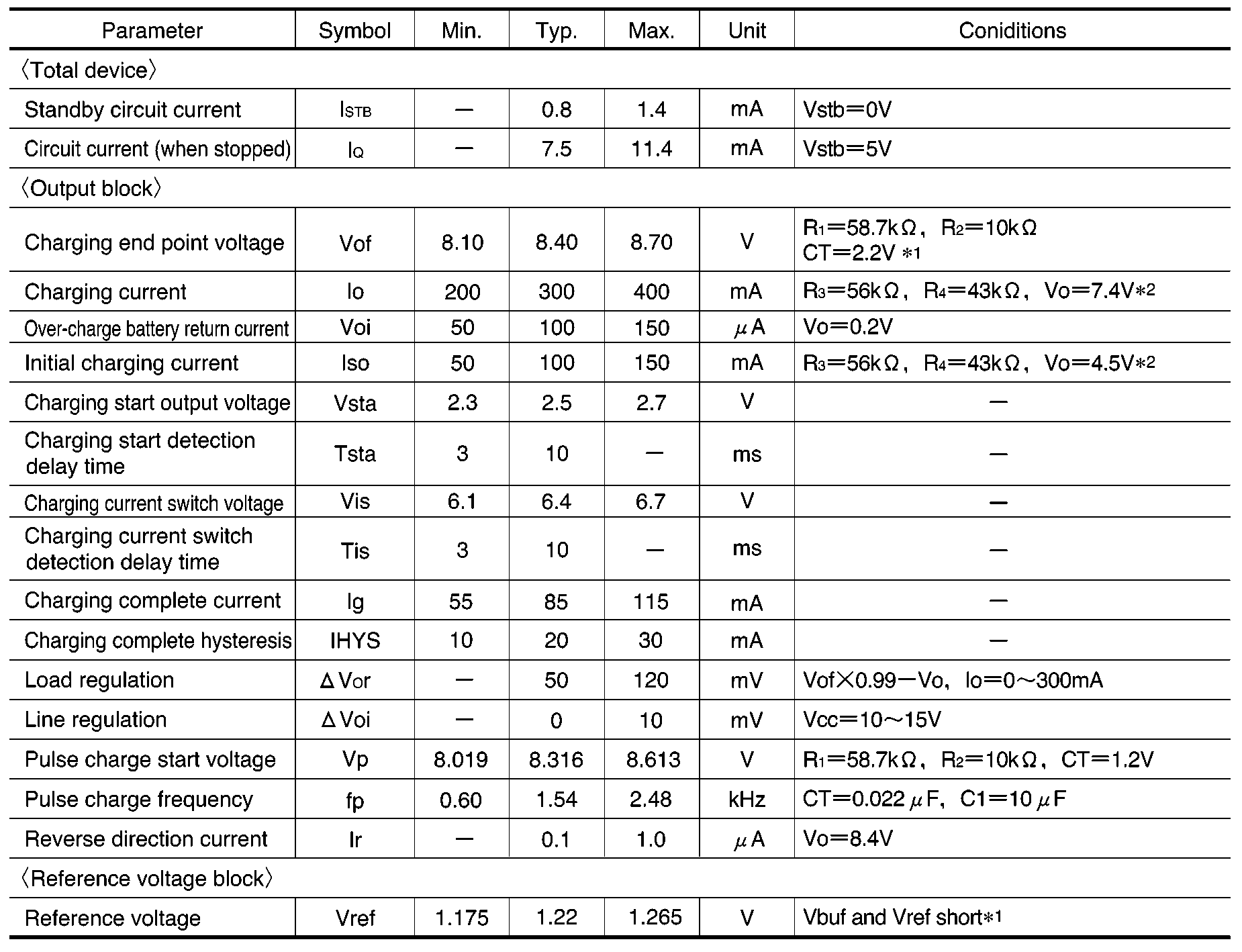
FElectrical characteristics (unless otherwise noted, Ta = 25_C, VCC = 12V, R1 = 58.7kΩ, R2 = 10kΩ)
Regulator ICs
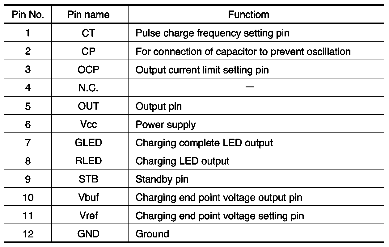
Do not use values other than CT = 0.022µF for the timing capacitor, and C1 = 10µF for the output capacitor.
For the output capacitor C1, use a tantalum capacitor with low capacitance variation with temperature, and a static
capacitance tolerance of ±10% or less. (3)
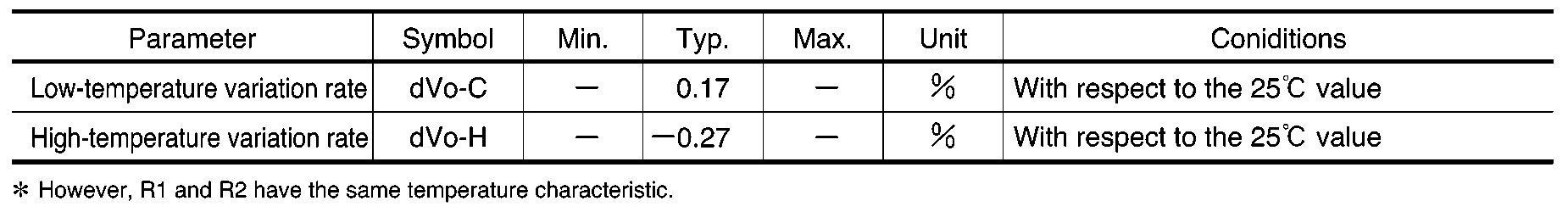
For the timing capacitor CT, use a film capacitor with low capacitance variation with temperature, a static capaci-
tance tolerance of ±10% or less, and a temperature variation rate of ±2% or less. Regulator ICs
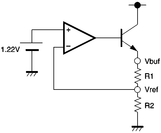
FExternal componentsSetting the “end point voltage”
Set the “end point voltage” Vbuf using resistors R1 andR2. Example:To set Vbuf to 8.4V:
1.22 = R2 / (R1 ) R2) 8.4R1 = 5.88 . . . R2
∗ For measurement of the electrical characteristics, Vref and Vbuf are
Regulator ICs
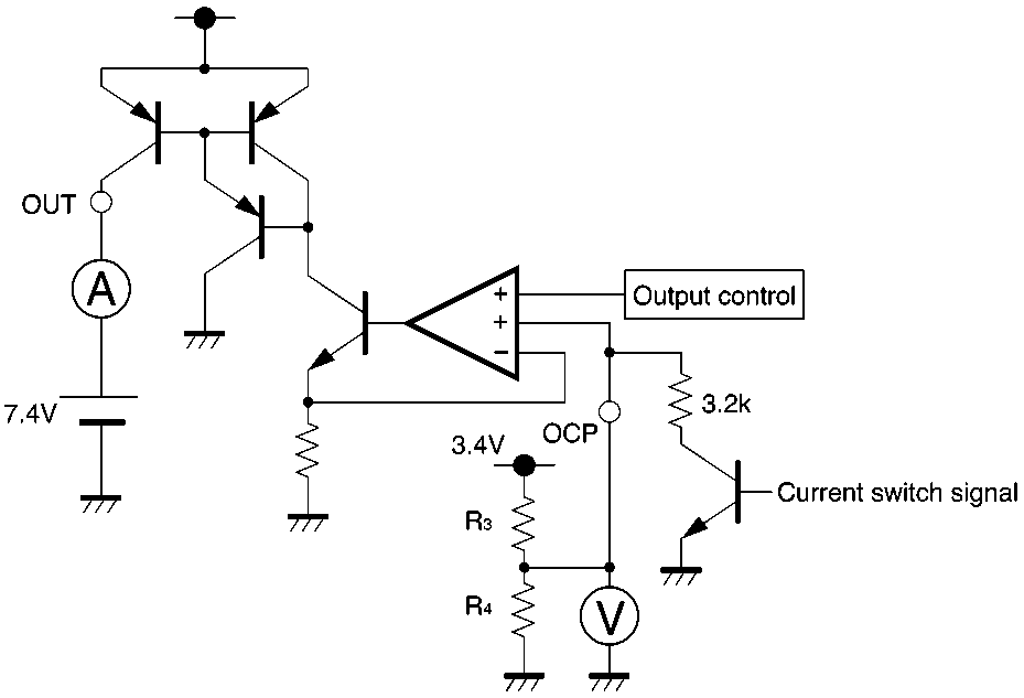
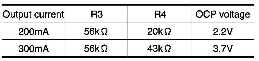
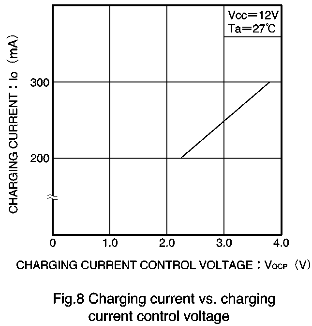
Set the value for the OCP voltage using R3 and R4(Ta =25_C, VCC = 12V, Vbuf = 8.4V, and Vo = 7.4V (Typ.))
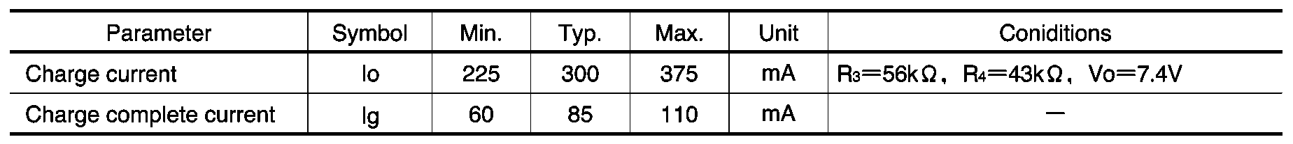
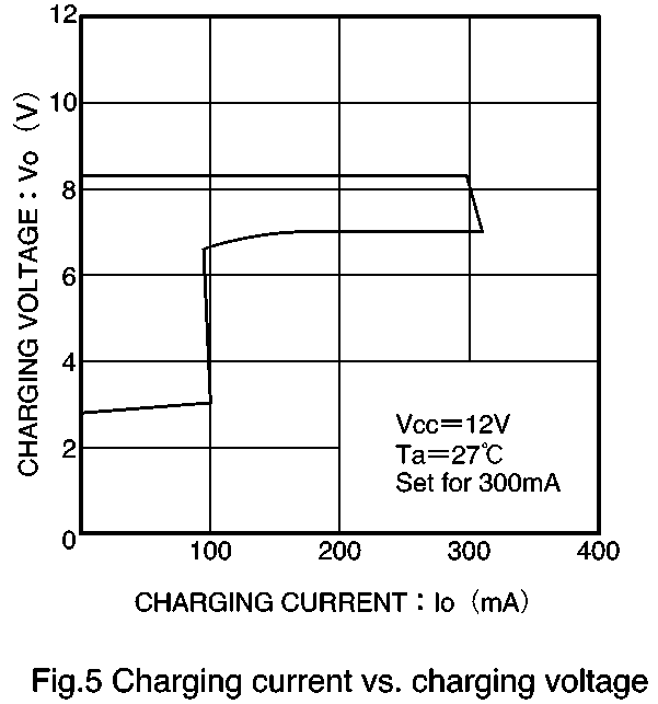
S Charging current and charge complete current for when the “end point voltage” is set to 8.4V ±50mV (Ta = 25_C and
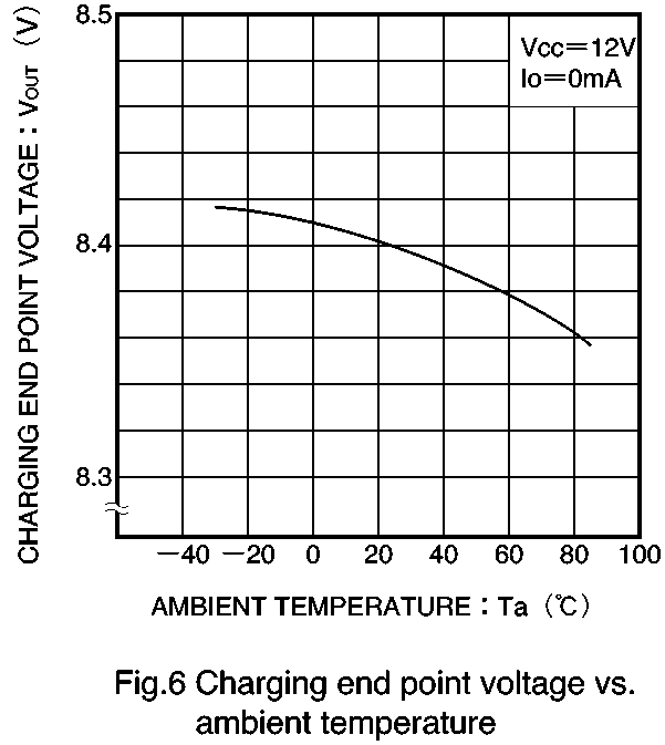
S Charge “end point voltage” temperature characteristic (VCC = 12V, R1 = 58.7kΩ, R2 = 10kΩ, and CT = 2.2V)
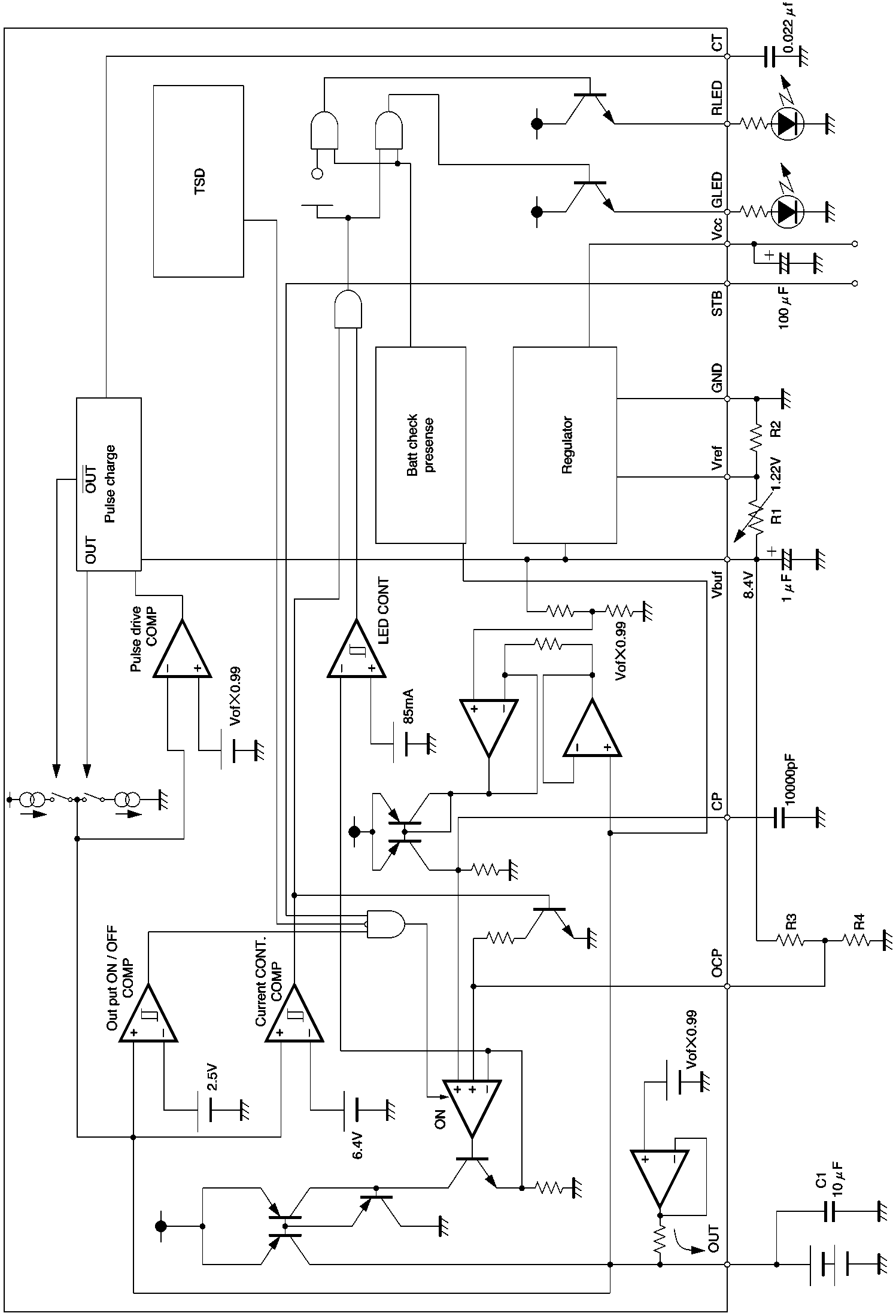
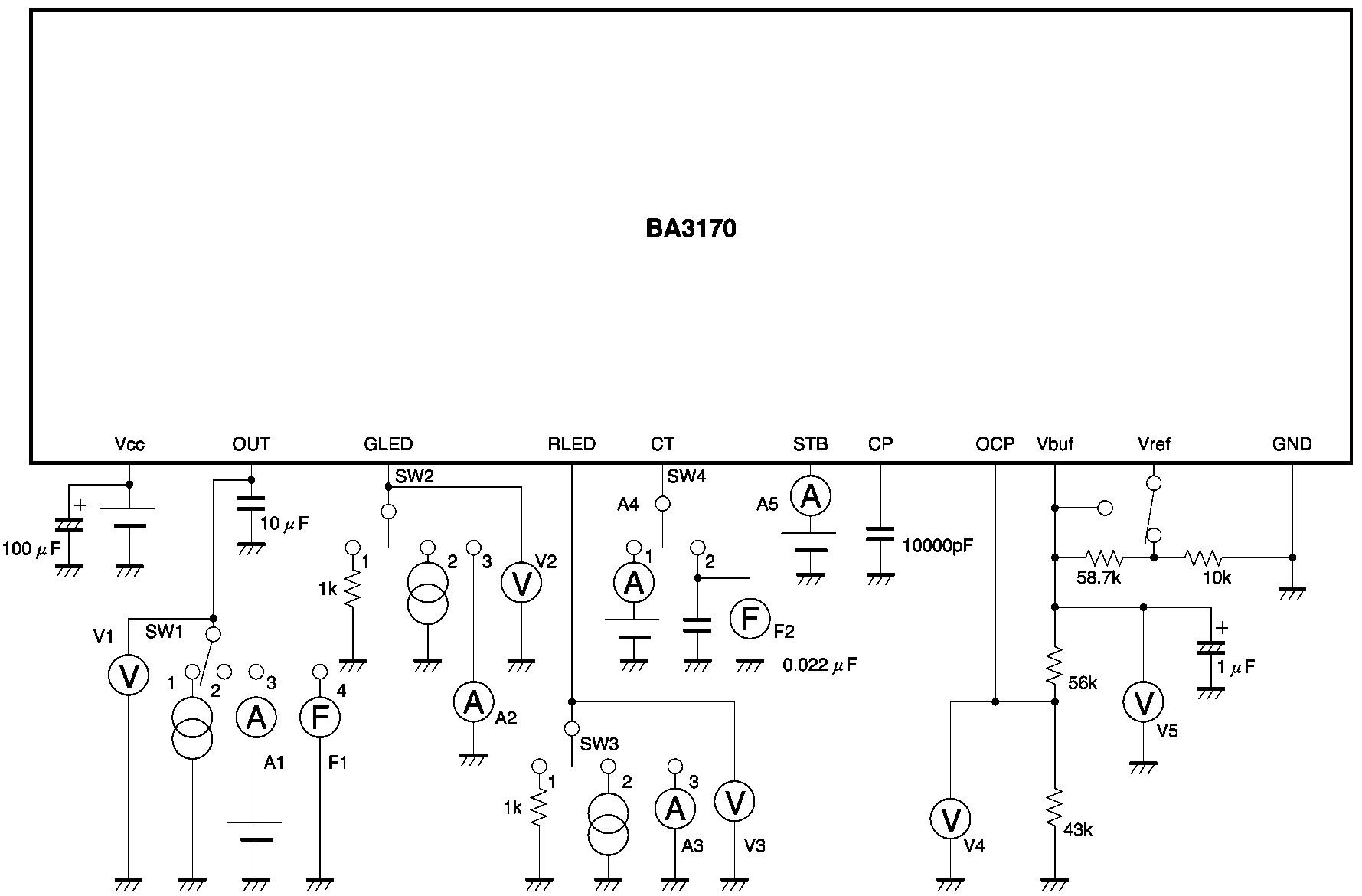
Application circuit (in the block diagram)
We guarantee the application circuit design, but recom-
Provided that the IC is operated within the recommended
mend that you thoroughly check its characteristics in ac-
operating voltage range, the operation of the circuit is
guaranteed within the allowed operating temperature
If you change any of the external component values,
check both the static and transient characteristics of the
With regard to the values for the characteristics, the rat-
circuit, and allow sufficient margin in your selections to
ing values for electrical characteristics cannot be guaran-
take into account variations in the components and ICs.
teed, but within these ranges there will not be a dramatic
Note that Rohm has not fully investigated patent rights
change in the values for the characteristics.
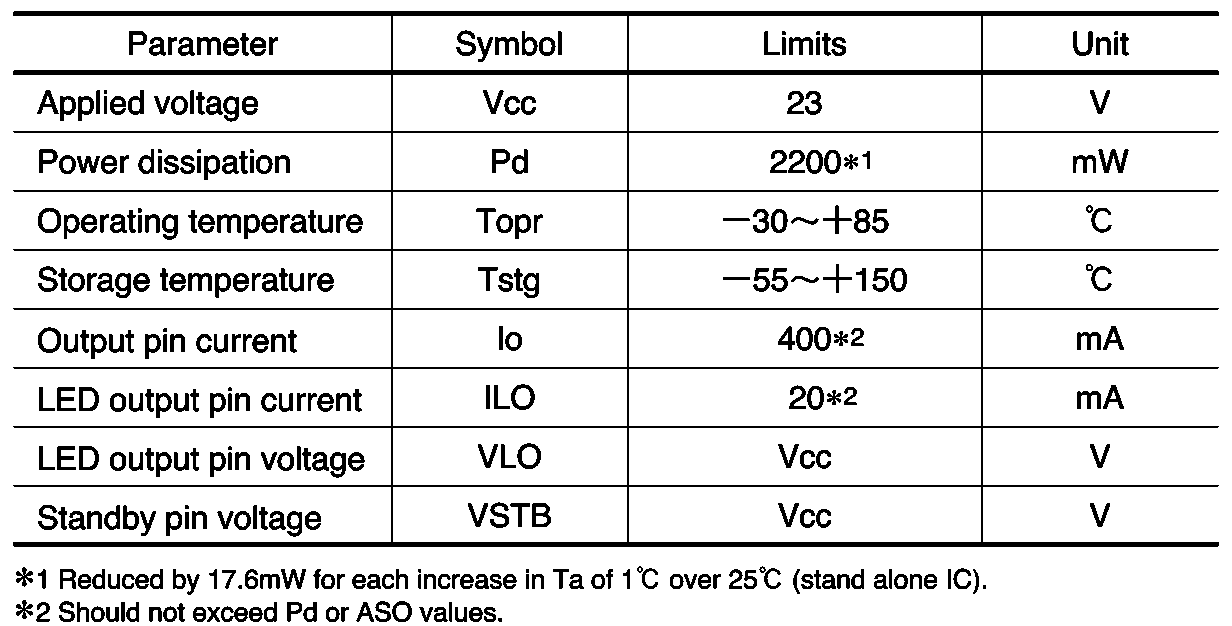
A derating characteristic is provided for power dissipa-tion. Your design should not require the component todissipate more than its maximum allowed power dissipa-tion over the operating temperature range. Regulator ICs
When the voltage between VCC (pin 6) and GND (pin 12)
With regard to the ground connections shown in the ap-
exceeds about 27V (at normal temperature), the over-
plication example circuit, make the PCB connections
voltage protection circuit switches all outputs off.
from each earth to the GND pin (pin 12) reasonably short,
Make sure to use the IC within this voltage limit.
and design your pattern layout to avoid electrical interfer-
Capacitors to prevent oscillation of the outputs
Be certain to connect capacitors between OUT (pin 5)
and ground, and CP (pin 2) and ground to prevent oscilla-
This IC includes a variety of protection circuits, but de-
tion. We recommend tantalum capacitors that have low
pending on the operation conditions, it may be possible
capacitance variation with temperature (particularly for
Exceeding the ASO will result in destruction of the IC, so
take due care to ensure that the ASO conditions are nev-
A thermal shutdown circuit is provided on the IC to pre-
vent it from being destroyed by high temperatures. When
(10) Great care has been paid to the quality of this com-
this circuit operates, all outputs go off, and when the tem-
ponent. However, due to the nature of lithium-ion batter-
perature drops to a certain level, operation resumes.
ies, if there is a risk of danger due to failure of this compo-
nent (e.g. fire or explosion), be certain to take appropriate
The outputs use PNP power transistors. When the VCC
measures in your design (fuses etc.).
(pin 6) voltage drops, even if the external capacitor on theoutput side causes the output-side voltage to exceed theVCC-side voltage, the IC will not be destroyed. Regulator ICs
Convidados / Invited guests / Invités LOGICALLY ILLOGICAL – INFORMATION AND INSIGHT INTO AUTISM COMO GARANTIR O SUPORTE ÀS PESSOAS COM PEA NOS MOMENTOS C2 DE TRANSIÇÃO? ESTRATÉGIAS PARA UM APOIO CONTINUADO AO LONGO DA VIDA Pinto Freitas, Paula THE EPIDEMIOLOGY OF AUTISM AND PERVASIVE DEVELOPMENTAL C2 DISORDERS Fombonne, Eric “HOW DO COGNITIVE THEORIES HELP US TO UN
Functional Safety, Quality Assurance, Project Management Aerospace, Automotive, E-Mobility, Machinery, Rail, Medical, IT Kompetenz- Profil Persönliche Daten Manfred Reiszner , Jahrgang 1974 Kurzprofil • Experte mit sehr gutem Know-How im Bereich Funktionale Sicherheit• Breite Erfahrung in Softwareentwicklung und Elektrik/Elektronik• Besonderes Wissen im Bereich Software Quali

 Regulator ICs
 Regulator ICs
 Regulator ICs
 Regulator ICs
 Regulator ICs
 Regulator ICs
 Regulator ICs
 Regulator ICs